Here are some tips to properly identify pneumatic fitting and component sizes when working on or retrofitting existing older machines.

Contributed by Kevin Kakascik, Technical Marketing Engineer, AutomationDirect
It’s just another typical day in your operations office, located right off the manufacturing floor. Demand for the company’s product is very high and the entire production team is working along at peak efficiency. In the recent months since this spike in demand, there really hasn’t been any unplanned downtime and that’s a good thing, because you really can’t afford that right now.
Of course, your optimism is interrupted when you hear a loud “POP” followed by a sustained “HISS.” Feeling like you have just been punched in the gut, you quickly walk out to the production floor where activity has ceased, and equipment is sitting idle. At the beginning of the production line near the first machine you see the maintenance supervisor with a push-to-connect fitting in his hand.
He says the fitting won’t hold the tubing, and a replacement fitting he pulled from stock won’t thread into the existing hole. His parting comment sounds ominous, “I don’t know how this happened, it’s just always worked for years with no problems, and now this is some kind of weird fitting.”
A senior maintenance technician with years of experience walks up just in time to hear the tail end of the conversation. He remembers the day this machine was put into production and asks to see the fitting. After a few moments of inspection he announces, “This is a 3⁄8 in. G-thread with an 8-mm push-to-connect fitting. This machine came from Europe about four years ago. I think I know where in our inventory we might have a fitting for this machine squirrelled away.”
But what if that technician was on extended sick leave or vacation? Worse, what if you didn’t even have someone like that on your maintenance staff? Or maybe, you don’t have the part in stock and the OEM is unreachable. How much money do you lose every minute when your production line is down because of a $2 part that takes only a few moments to replace?
Pneumatic equipment is well known for reliability and ruggedness, but years of uninterrupted operation can create complacency when it comes to stocking parts. Sometimes these machines seem to last forever, other times they last long enough for the team to forget everything they’ve known about spares, and then one small part failure takes down production with an unplanned outage. But when all else fails, you can follow a few basic steps to figure out what you have, and even how to source a part yourself if need be.
Measure up
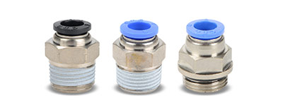
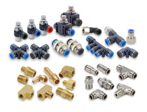
Identifying the type and size of a pneumatic fitting, or the hardware it goes into, can be difficult without the right knowledge and tools. At a glance, many thread and tubing combinations appear similar, especially when comparing metric to other standards sizes used in North America (Figure 2).
It is important to correctly identify the necessary size not just for fittings, but for solenoids, manifolds, cylinders, valves, air preparation units, and all other pneumatic components. At a minimum you should obtain a caliper for making measurements, although sometimes you can get by with a good ruler and close inspection.
Here are the basic steps to determine necessary fitting sizes.
Step 1: Determine the gender, male or female
It sounds simple and intuitive, but this is easy to get wrong when in a hurry, or to write down information incorrectly. If the threads are on the outside of the fitting it is male; if the threads are on the inside of the fitting it is female.
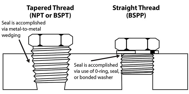
Step 2: Determine if the threads are straight (parallel) or tapered (Figure 3)
This distinction can be a little harder to spot. There are several thread designs:
- National Pipe Tapered (NPT)
- National Pipe Straight (NPS)
- British Standard Pipe Taper (BSPT), also known as R thread
- British Standard Pipe Parallel (BSPP), also known as G thread
- Metric, Tapered or Straight
Only a few of these are prevalent and typically used with pneumatic equipment. Note that NPT/NPS and BSPT/BSPP both use imperial measurements for threads, but BSPT/BSPP uses metric tubing sizes.
To determine whether threads are tapered or straight, use calipers to measure the outside diameter (OD) of the threads at the first, fourth, and final thread. For a female fitting, measure the inside diameter (ID) of the threads at the same intervals. With this information, make the following determination:
- Tapered threads will have a smaller measurement at the first thread than at the final thread.
- Straight threads will have the same three measurements
NPT and BSPT are very similar and hard to distinguish visually. They do have slightly different taper angles, but NPT threads have a 60° thread angle with flattened peaks and valleys, while BSPT has a 55° thread angle and rounded peaks and valleys. The pitches are close to the same but not compatible.
Here are some good rules of thumb for pneumatic equipment, which should always be confirmed with further detailed measurements:
- NPT threads are most commonly used in machinery built in the U.S.
- If the tubing side of a fitting is metric, then the fitting is probably BSPT or BSPP
- BSPT is most commonly found on Chinese and Japanese machinery
- BSPP is most commonly found on European machinery
Step 3: Determine the thread pitch
The thread pitch defines the distance from the peak of one thread to the next. It may be expressed in some tables as an inch or mm measurement from thread to thread, or in other tables as to how many threads fit into a one-inch distance.
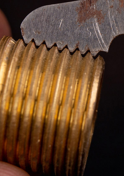
Because many pitches are quite similar but not an exact match, best practice is to use a pitch gauge, a sawtooth-like measuring tool with blades matching common sizes (Figure 4). One can simply try different sizes until an exact match is found.
If no pitch gauge is available, a workaround is to use a caliper or very fine ruler to measure the distance of a number of threads, then do a little math as needed.
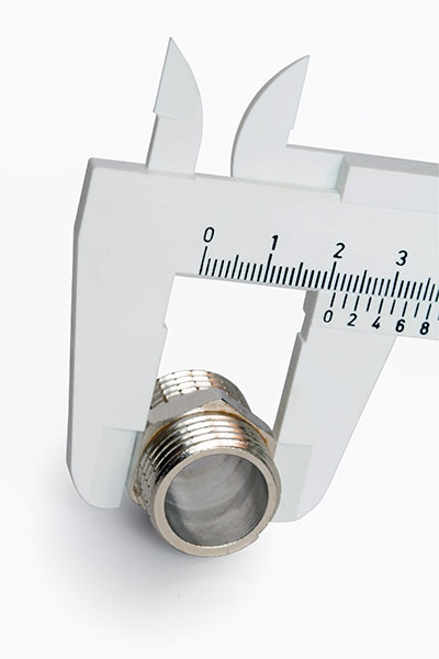
Step 4: Determine the thread diameter
Use calipers to measure the OD of male threads, or the ID of female threads (Figure 5). Take this measurement at the largest diameter of the thread, female fittings measured at the first thread and male fittings measured at the last thread.
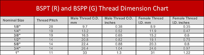
Step 5: Determine the fitting size
Compare data obtained in steps 1 through 4 with charts like Figure 6, to identify the fitting size.
Hoses and tubing
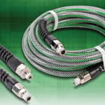
The preceding steps have discussed the threaded part of a fitting, but many fittings transition to hose or flexible tubing and must be sized on that end also.
A simple and common fitting used with hoses is called a barbed fitting, which will have one or more ridges and is designed to push into the hose and grip it. There aren’t any industry standards for small barbed fittings, so when looking for a replacement one must pay attention to the design of the existing fitting, especially the number of barbs. It is possible to measure the OD of the barbs, but barbs work by stretching the hose to make a seal, so the barb must always have a slightly larger OD compared with the tubing ID.
Hose is generally specified by the inside diameter. Blow-off force is a function of how flexible the hose is (durometer), where a softer (lower durometer) hose will grip better. In many installations, a hose clamp is added to hold the hose more firmly onto the barbed connection.

Flexible tubing can also be used with push-to-fit fittings. For these, simply measure the existing tubing OD or the fitting ID with calipers. Although some OEMs may color code tubing by size, there are no industry standard colors for tubing sizes or materials. If you are lucky, the tubing will have factory size markings.
Another tube measurement trick is to use a drill bit gauge to determine the OD, or use various drill bits to find the ID. Remember that if you don’t find a perfect fit, you may be using imperial drill measures but the product is metric, or vice versa. For accurate readings, avoid stretched areas of tubing.
One other tip for pneumatic machinery is that there are two cases where imperial and metric tubing sizes match so closely they are interchangeable:
- 5/32 in. is the practically the same as 4 mm
- 5/16 in. is the practically the same as 8 mm
Avoid downtime by being prepared
Because pneumatic machinery can be very reliable, some facilities may not carry adequate spares. But with the right tools and knowledge, determining fitting and tubing types and sizes isn’t all that tough. Measurement accuracy is of utmost importance as many of the thread diameters and pitches are very close to each other but not interchangeable. With the right information in hand and a good supplier website, you can quickly order the parts you need to get back into production.
AutomationDirect
automationdirect.com


Leave a Reply